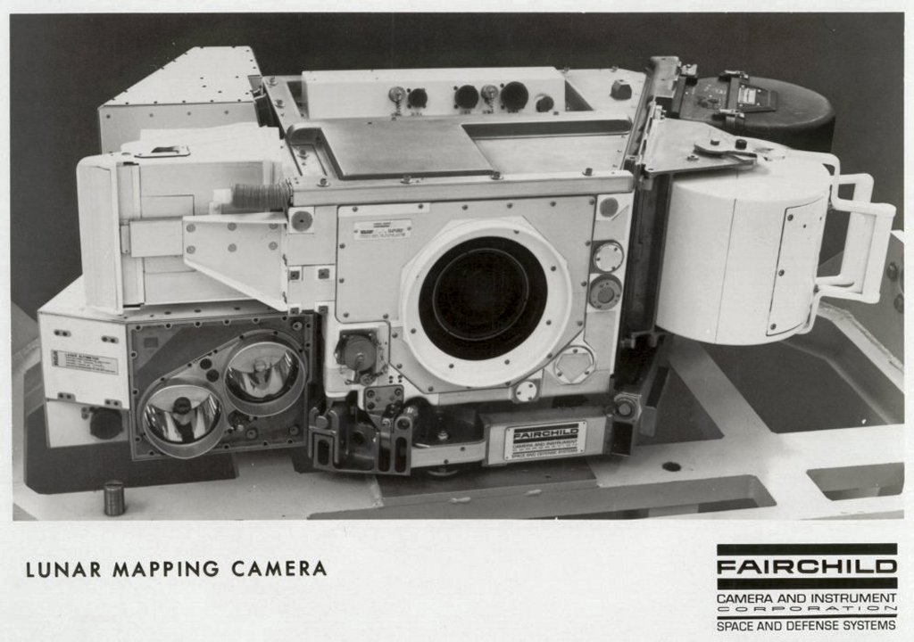
The Fairchild Lunar Mapping Camera
The terrain frame camera was designed to acquire high resolution lunar surface photography, whilst simultaneous time correlated stellar photography was acquired by the stellar camera. This stellar photography was used in post flight data acquisition for camera attitude determination, as the optical axis of both camera’s and their relative orientation to one another are known and calibrated. Additionally the laser altimeter was directly mounted to and aligned with the Lunar Mapping Camera, which provided altitude data for the area which is coincident with the centre of each terrain camera exposure. The viewing spot of the laser altimeter was calibrated within the terrain frame format.
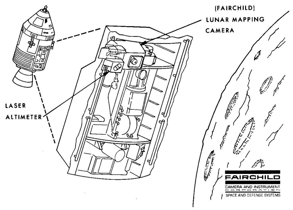
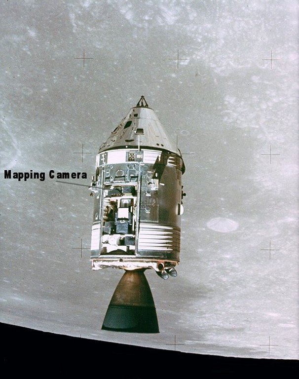
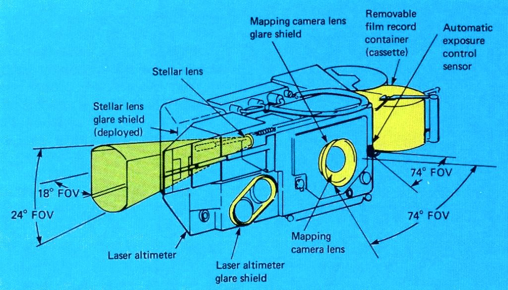
When on station in orbit around the Moon, the Lunar Mapping Camera is deployed (extended) from its storage location in the SIM bay, in order to provide a clear field of view for the stellar camera. When deployed the stellar camera's glare shield is extended. The Lunar Mapping Camera only remains deployed whilst in use. When not in use it is retracted to it’s storage position in the SIM bay, so as to avoid interference with other experiments mounted in the SIM bay. See the illustration and photograph below.
Click on above image to enlarge,
Click on above image to enlarge
The Lunar Mapping Camera is finally retracted once the photographic mission is completed, soon after the Trans-Earth Injection (TEI) burn to commence the coast back to Earth.
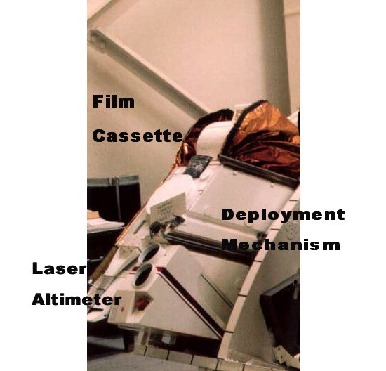
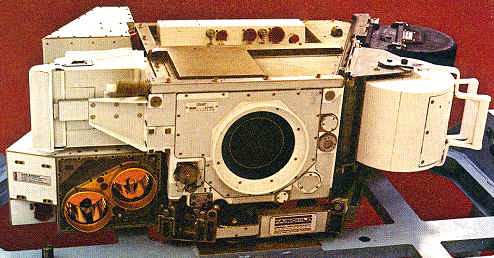
The Lunar Mapping Camera Subsystem consists of interlock metric and stellar cameras, whose optical axes and orientation relative to one another are fixed and measured, along with a laser altimeter. See below a photograph of the Lunar Mapping Camera Subsystem mounted to a test bench.
Click on above image to enlarge
The stellar camera, on the other hand, has a 3-inch (76-mm) focal length, f/2.8 lens. The format is 1¼ inches x 1 inch on 35-mm film and the stellar coverage is a 24° cone with flats. Exposure time for the stellar camera is 1.5 seconds fixed. Film capacity for the stellar camera is 510 feet (155.4 metres) compared to the 1,500 feet (460 m) capacity for the metric camera. The critical interlock angle between the metric and stellar cameras is 96°. Correspondingly, the laser altimeter is mounted with transmission and receiving optical axes parallel to those of the metric camera.
The laser altimeter measures the precise altitude of the CSM above the lunar surface. It can function either with the metric mapping camera or independently. When in camera imaging mode, the laser altimeter is synchronised with the image exposure time, which varies from 20 to 28 seconds, which corresponds to 30 to 43 km travel on the lunar surface between exposures. When in the independent mode the laser altimeter functions every 20 seconds. The laser altimeter weighs approximately 50 lbs (22.5 kg), consisting of a ruby laser, transmitting and receiving optics, and a range counter. The laser pulse projected at the lunar surface emanates from a 16-power refracting telescope with a beam diameter of 4.0 inches. (101.6 mm). At the lunar surface, the beam diameter is 30 metres for a spacecraft altitude of 100 km. A small portion of the laser output is applied to a photodiode to generate the start pulse, which is then sent to the range counter. The range counter counts in increments of 6.67 nsec, providing 1m resolution. The return pulse, which has been reflected by the lunar surface below, is focused on a photomultiplier tube through the receiving telescope. The electrical output from the photomultiplier stops the range counter.
The illustration below shows the photo coverage geometry.
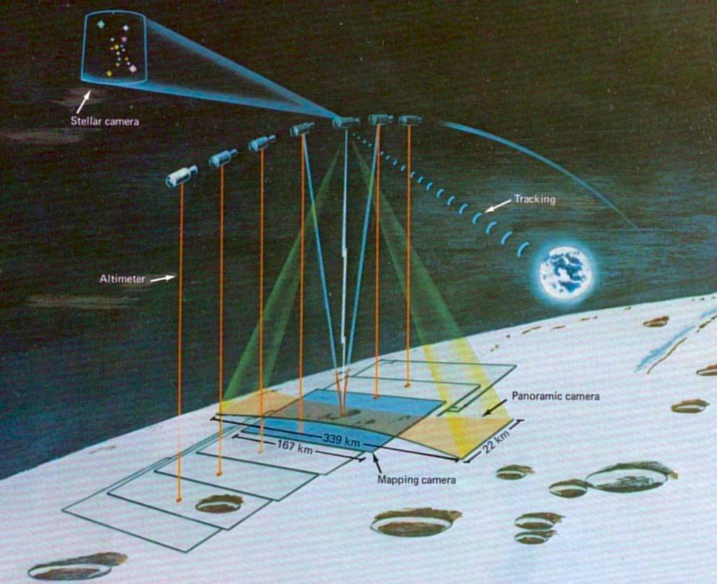
Click on above image to enlarge.
For mapping imagery, vertical photography was obtained. In order to increase the area covered some imagery was obtained obliquely to the North and South of the ground track with a limited quantity of frames taken in forward and rear oblique attitude. The oblique photography was of little use for mapping.
The illustration below is of a segment of a map produced by the Aeronautical Chart and Information Center, of the United States Air Force for NASA, showing samples of the ‘footprint’ of the mapping camera. The example shown is from Apollo 16.
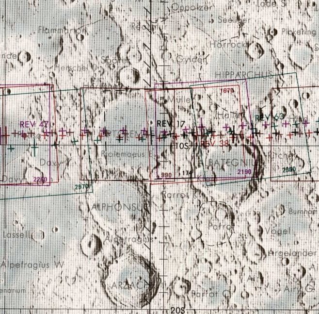
Click on above image to enlarge.
The mapping and stellar cameras record reference and dynamic auxiliary data on each of the image frames. The reference data consists of fiducial marks and reseau crosses. The fiducial marks on the mapping camera images are illuminated both naturally and artificially. The naturally illuminated array of reseau crosses on the mapping camera images are spaced at 10-mm centres, whilst the those on the stellar camera images are spaced at 5-mm centres and illuminated artificially. These reseau crosses assist in determining post-mission film shrinkage. The dynamic auxiliary data for both cameras is made up of binary coded time and altitude words which are recorded adjacent to each image frame. The mapping camera also gives the exposure time of each image frame and indicates whether FMC was present or not.
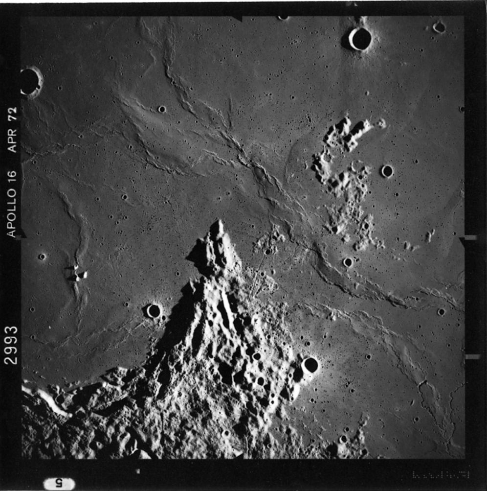 | 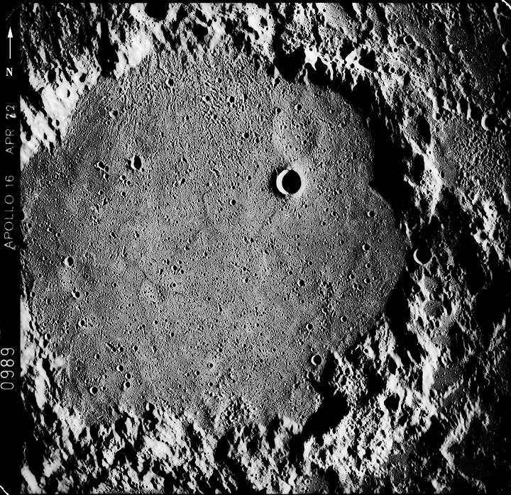 | |
| AS16-2993M | AS16-0989M | |
| Letronne crater | Ptolemaeus crater |
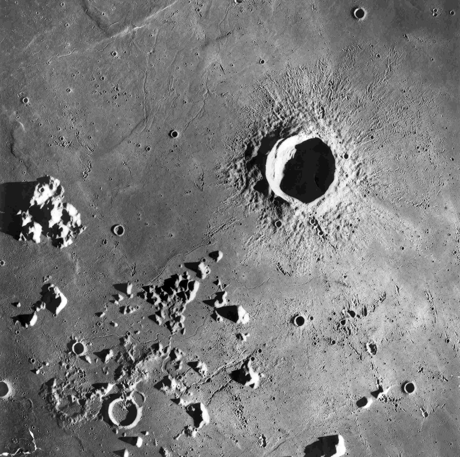 | 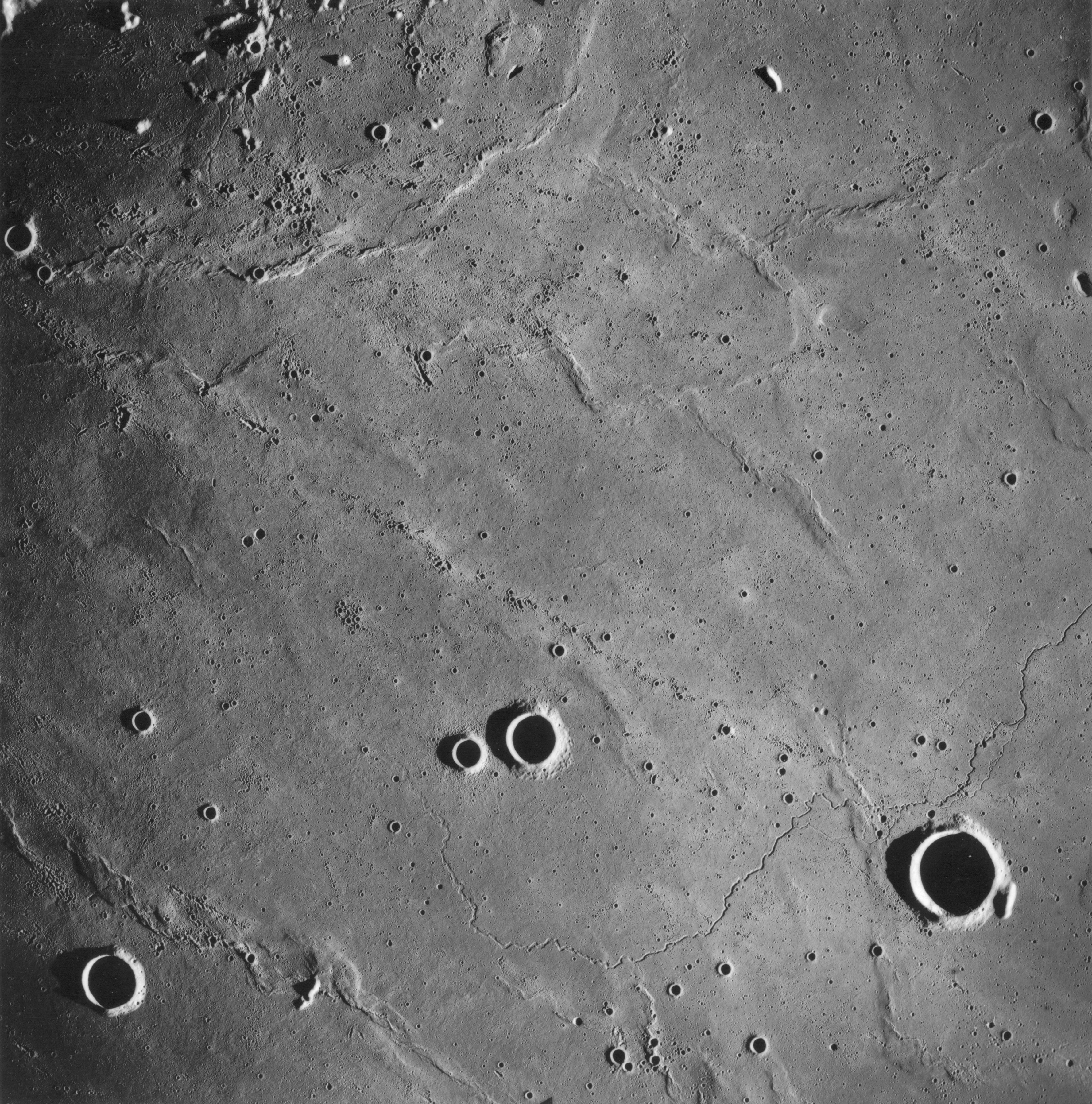 | |
| AS17-2730M | AS17-2930M | |
| Euler crater | Brayley crater |
Hardcopies of the photographs taken by the Lunar Mapping Camera and maps derived from it's images can be obtained from the National Space Science Data Center at http://nssdc.gsfc.nasa.gov
Mapping camera photography was used amongst other things to produce topographic photomaps of the lunar surface. See below for an example of part of one such map.
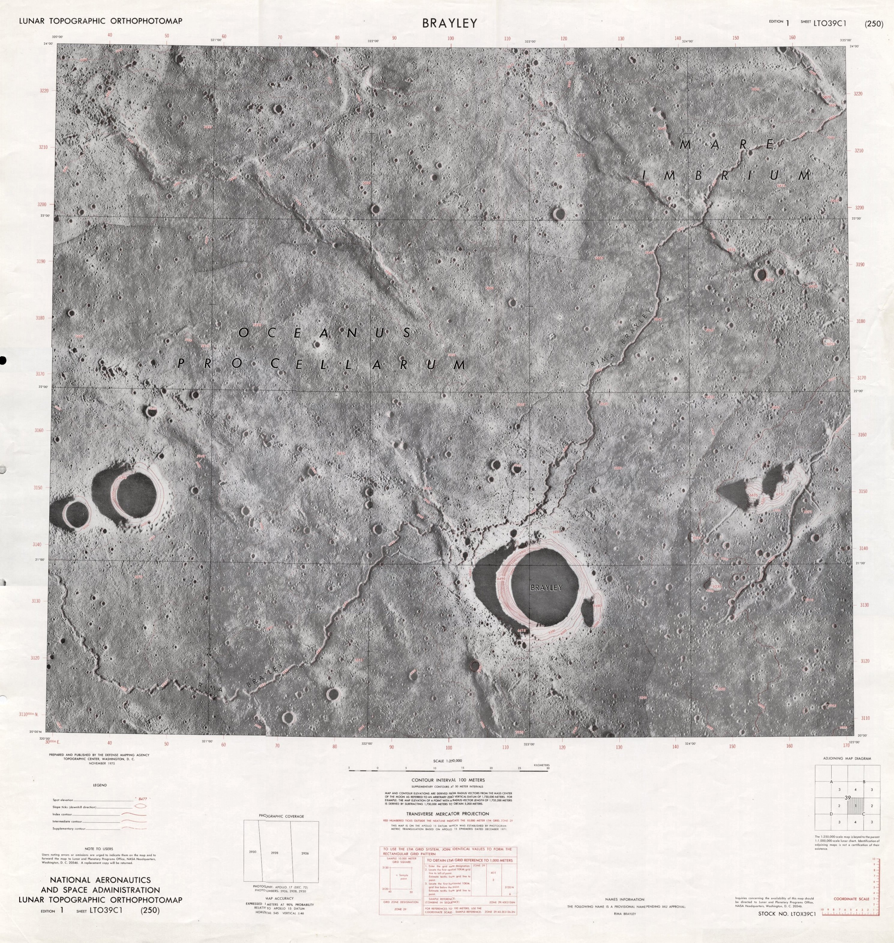
Click on above images to enlarge.
The map above on the right is LTO39C1, produced at an original scale of 1:250,000, covering the area adjacent to the crater Brayley in Oceanus Procellarum. See the Mapping Camera photograph AS17-2930 as above which was used to produce part of this map.
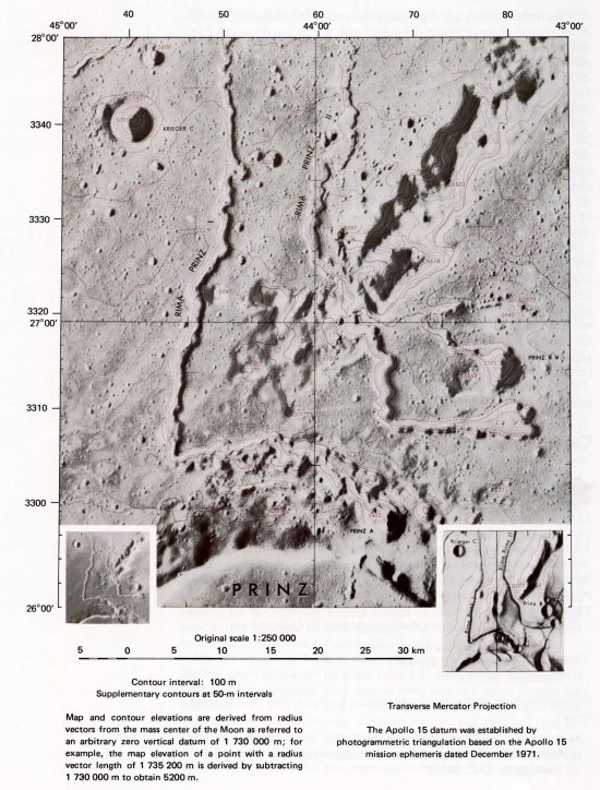
Geological maps were also produced using the imagery obtained by the Mapping camera. Below is an example showing the Apollo 17 landing area, compiled using Apollo 15 Mapping camera images.
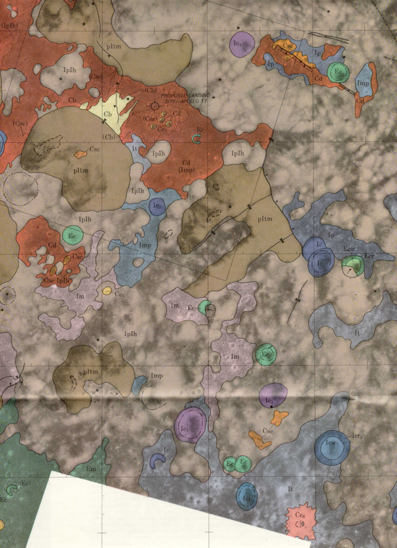
Click on above image to enlarge
Copies of some of the geological maps produced can be obtained from the U.S. Geological Survey at http://mac.usgs.gov/isb/pubs/booklets/usgsmaps/usgsmaps.html
| Type | Stationary film, mapping |
| Mode of Operation | Autocycle |
| Lens (Mapping) | 3 inch (76 mm) f/4.5 |
| Lens (Stellar) | 3 inch (76 mm) f/2.8 |
| Format (Mapping) | 4.5 x 4.5 inch (114 x 114 mm) |
| Format (Stellar) | 1.25 inch (31.75 mm) diameter with 0.96 inch (24.4 mm) flats |
| Mapping Coverage | 74° x 74° |
| Film (Mapping) | 5 inch (127 mm) 2.5 mil base non-perforated |
| Film (Stellar) | 35 mm, 2.5 mil base non-perforated |
| Altitude (Lunar) | 30 to 80 nautical miles (56 to 148 km) |
| Film Capacity (Mapping) | 1,500 feet (460 metres) |
| Film Capacity (Stellar) | 510 feet (155.4 metres) |
| Cycle time (Mapping) | 8.25 to 33.0 sec/cycle |
| Cycle time (Stellar) | 8.25 to 33.0 sec/cycle |
| Exposure Time (Mapping) | 1/15 to 1/250th second |
| Exposure Time (Stellar) | 1.5 sec (fixed) |
| Aperture | Fixed on both cameras |
| Exposure Control | Automatic between lens shutter |
| Forward Motion Compensation (Mapping only) | 0.03 to 0.12 inches/sec (0.76 to 3.05 mm/sec) |
| Dynamic Resolution | 80 lines/mm AWAR, 3.0 contrast, EK 3404 film (Both cameras) |
| Distortion (Mapping) | plus or minus 50 microns radial, 5 microns max tangential |
| Distortion (Stellar) | plus or minus 10 microns radial, 5 microns max tangential |
| Data Recording | Reseau, Fiducial, Camera Serial Number, Index Word, Coded Time, Altitude, Shutter Speed, FMC On/Off, Start of pass |
| Size | 33 inches high x 45 inches wide x 15 inches long (838 x 1,143 x 381 mm) |
| Weight | 275 pounds (125 kg) |
| Power | 28V DC, 2 amps |
Apollo 15 CM Software - Delco Electronics, 1971
Apollo 15 Press Kit - NASA 71-119K, July 1971
Apollo 15 Mission Report - NASA MSC-05161, December 1971
On the Moon with Apollo 16, Gene Simmons - NASA EP-95, 1972
On the Moon with Apollo 17, Gene Simmons - NASA EP-101, 1972
Apollo 15 Preliminary Science Report - NASA SP-289, 1972
Apollo over the Moon, Harold Masursky, G. W. Colton, Farouk El-Baz - NASA SP-362, 1978
North American Rockwell - Space Division, Fact Sheet SP-29, 1972
Chariots for Apollo: A History of Manned Lunar Spacecraft. C. G. Brooks, J. M. Grimwood, L. S. Swenson jnr - NASA SP-4205, 1979
Where No Man Has Gone Before: A History of Apollo Lunar Exploration Missions. William Crompton - NASA SP-4214, 1989
National Space Science Data Center

Last update: 2017-02-17
|
|
|
|
Return to SIM Bay Cameras |
The Itek Panoramic Camera |